Step-by-Step Instructions:
Step 1: Soak nuts on exhaust flanges and coupler clamps overnight with penetrating oil.
- If your car has the original exhaust fasteners, they will likely be extremely seized.
- Soak the nuts and bolts on the exhaust flanges and coupling clamps overnight with a penetrating oil such as WD-40 Specialist Penetrant.
Step 2: Gather all required tools and parts
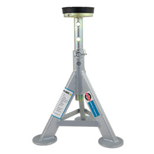
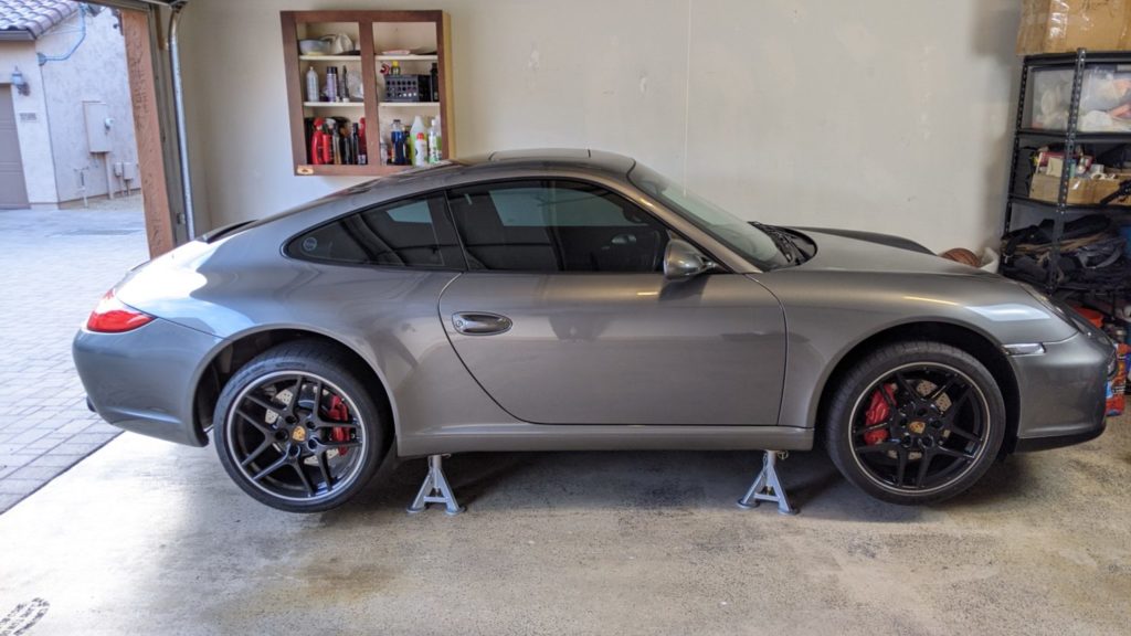
Step 3: Raise vehicle on jack stands
- To give yourself enough clearance to work, safely raise your vehicle using a lift or jack and jack stands; ensure your car is level.
- If using jack stands, you just need to raise the rear of the vehicle.
- NEVER rely on a jack to keep your car up; use jack stands to safely support your vehicle.
- Also be sure to use wheel chocks to prevent your car from rolling.
- Once your car is on jack stands, give your car a hard shove to make sure it is secure.
- To lift your vehicle on jack stands, check out this helpful YouTube video.
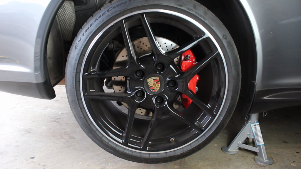
Step 4: Remove rear wheels
- Use a 19mm socket to remove the wheel bolts.
- It is helpful to use a wheel guide bolt to remove and reinstall your wheel.
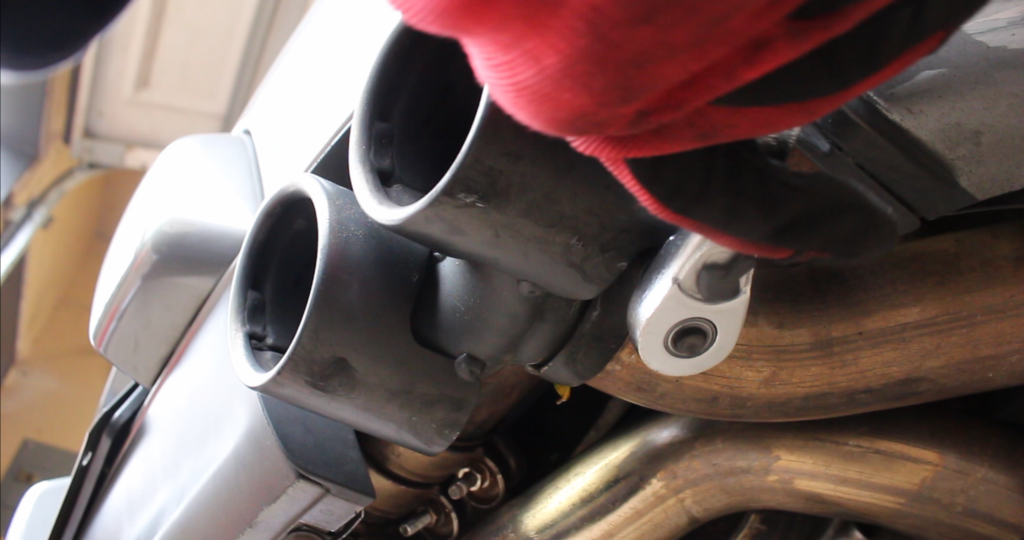
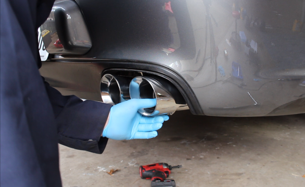
Step 5: Remove the exhaust tips.
Loosen each exhaust tip clamp using an E8 external torx socket.
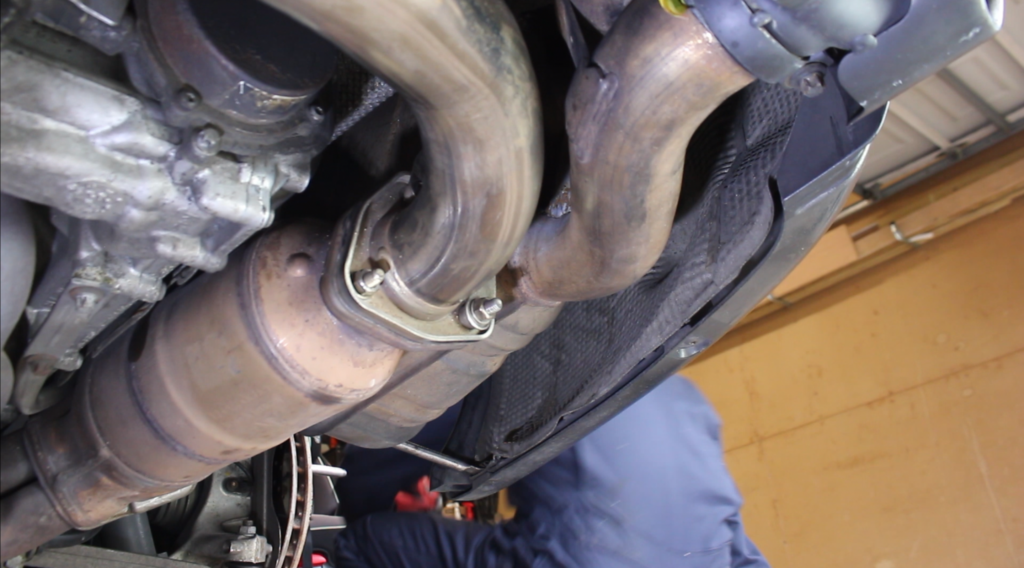
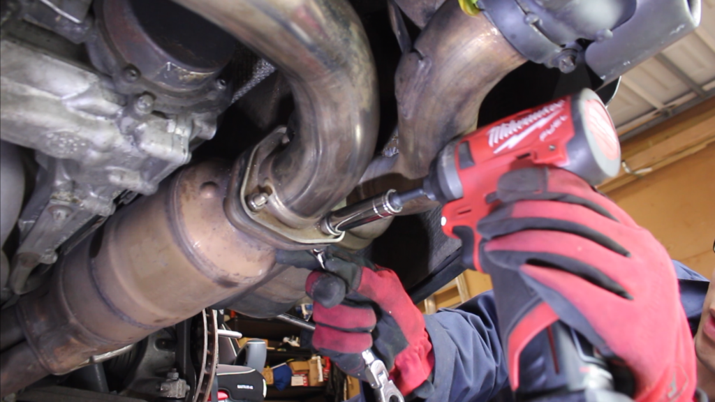
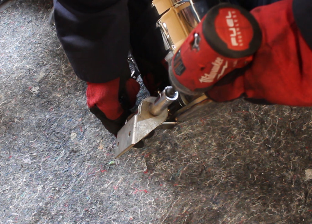
Step 6: Remove center muffler exhaust flange nuts (3 on each side)
- The exhaust flange nuts and bolts will likely be seized. Soak the nuts in penetrating oil and let sit for 10 minutes before attempting to remove the nuts and bolts
- Use a 13mm socket to remove the lower to nuts.
- To access the top nut, you will need a 13mm S wrench or a 13mm socket connected to a universal joint, really long extension, and a ratchet.
- Note: If the nuts feel like they will strip, tighten them instead until the bolt snaps. Then, use a ball joint separator to push the bolts out.
Step 7: Disconnect each side muffler from the center muffler
- Each muffler is connected to the center muffler via an exhaust coupler; apply a liberal amount of penetrating oil to the 13mm nuts on each coupler.
- Using a 13mm socket and long extension, remove the 13mm nuts on each coupler.
- If the nuts feel like they are going to strip, tighten them instead to break the bolts.
- Once the nuts are off, slide the exhaust couplers onto the side muffler pipes to disconnect them from the center muffler.

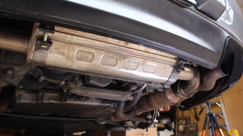
Step 8: Remove the center muffler
- Loosen the remaining two center muffler support brackets using a 6MM allen bit.
- Once the brackets are loose enough, slide each one outward outward onto the center muffler pipe.
- Carefully drop down and remove the center muffler.
Step 9: Next, start removing the side muffler.
Remove the bumper support brace, which is held on by a T30 torx on the bottom and 10mm bolt on the top.
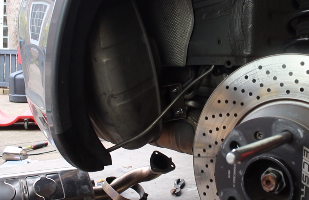
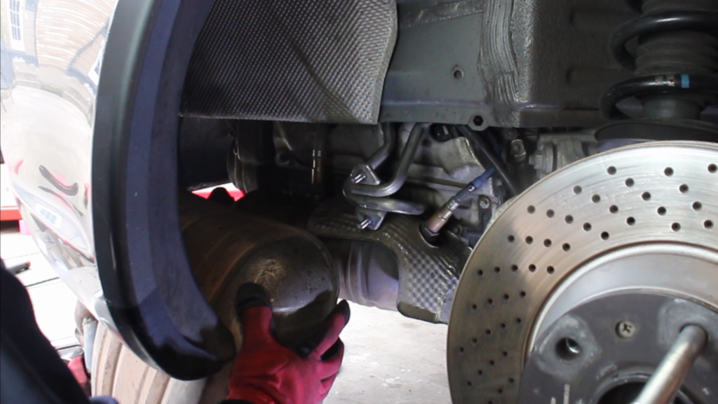
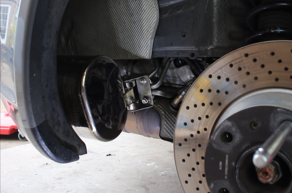
Step 10: Disconnect the muffler from the muffler support.
From the wheel well, remove the two 13mm nuts that hold the side muffler support bracket in place.
Step 11: Remove the side muffler.
- Carefully remove the muffler support bracket from the studs, so you don’t damage the threads.
- Lower the muffler from the bottom of the bumper and remove it.
Step 12: Remove the remaining muffler following the prior steps.
Step 13: Transfer the muffler support brackets from the original mufflers to the ECG Performance mufflers.
Start by removing the 13mm nut and bolt holding each support bracket in place.
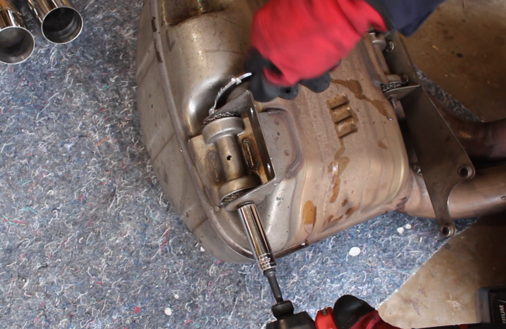
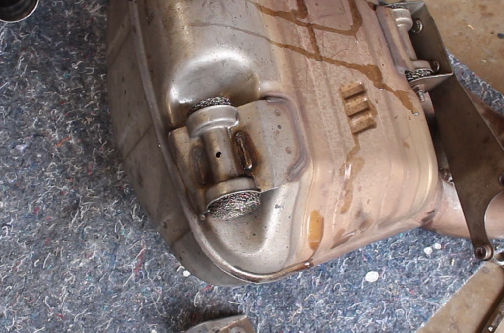
Step 14: Remove the muffler bracket mounts (the steel wire mesh pieces) as well.
- Wear thick gloves when handling the muffler bracket mounts.
- If necessary, use pliers to gently remove the muffler bracket mounts.
Step 15: Install the muffler bracket mounts and muffler support brackets on the ECG Performance mufflers.
Torque the 13mm fasteners to 17 ft-lbs.
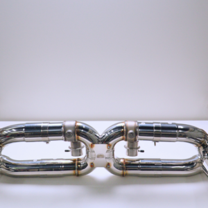
Step 16: Now it's time to begin install the ECG Performance exhaust system. Start by installing one of the ECG Performance mufflers.
- Raise muffler up from underneath the bumper.
- Position muffler support bracket in place and secure in place with new 13mm flange nuts (PART LETTER). Do not fully tighten yet.
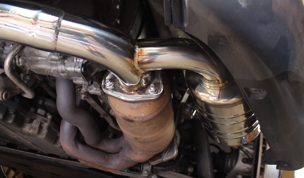
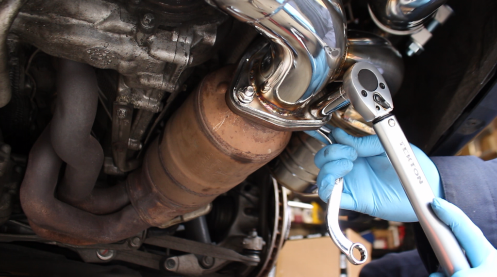
Step 17: Install new exhaust gasket (PART LETTER) and secure new muffler to catalytic converter flange.
- Use the supplied fasteners (PART LETTER) for the exhaust flange.
- The washer should be on the nut side.
- Do not fully tighten fasteners yet.
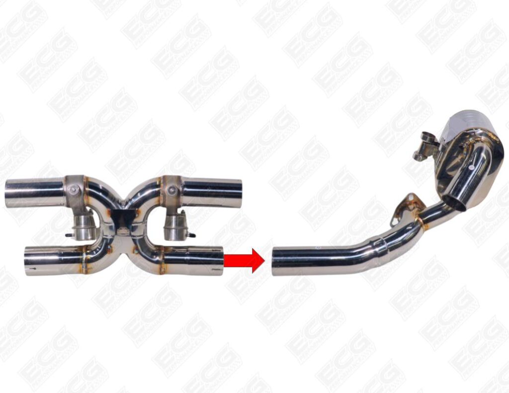
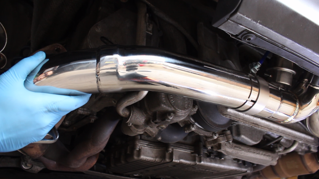
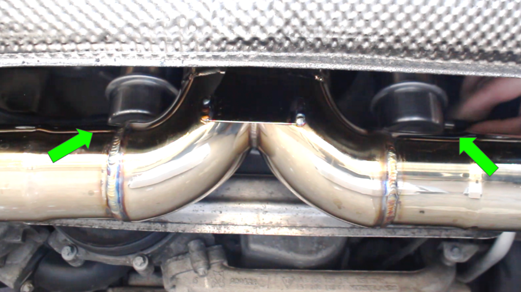
Step 18: Connect the center muffler section to the side muffler as shown.
- Add exhaust clamps to the lower center muffler section pipes
- Then slip the center muffler section onto the side muffler pipe.
- For now, rotate the center muffler section towards the front of the car as far as it can go.
Step 19: Connect the remaining ECG Performance muffler to the center muffler section.
- Slip pipe going towards the center of the vehicle onto the center muffler section.
- Install new exhaust gasket and fasteners (PART LETTER).
- Secure muffler support bracket with new 13mm flange nuts (PART LETTER).
Step 20: Secure ECG Performance mufflers in place.
- With the exhaust flanges centered with the catalytic converter flanges, torque the 13mm fasteners to 22 ft-lbs.
- Torque the 13mm flange nuts on the muffler support brackets to 17 ft-lbs.
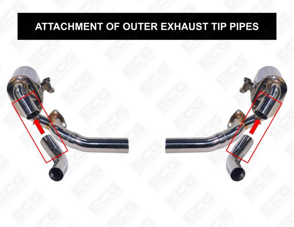
Step 21: Install the outer exhaust tip pipes on the side mufflers.
- Add exhaust clamps to outer exhaust tip pipes (PART LETTERS)
- Slip on the exhaust tip pipes onto the side mufflers
- Tighten clamps just enough to secure pipes while allowing you to still adjust them.
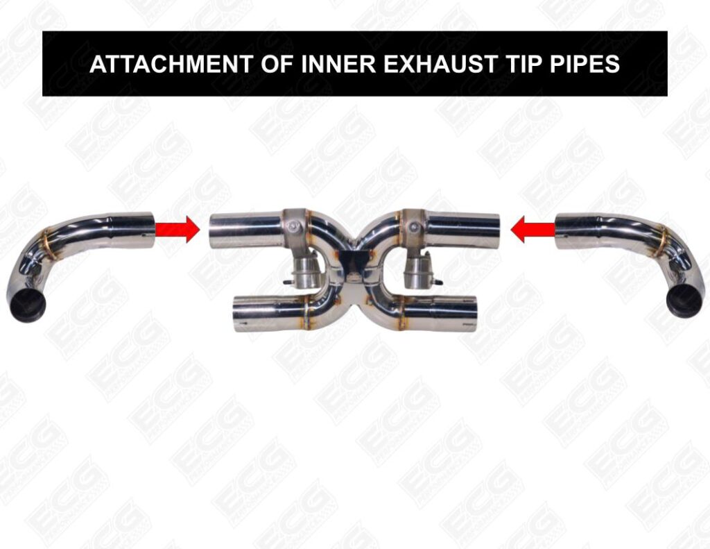
Step 22: Install the inner exhaust tip pipes onto the center muffler section as shown.
- Add exhaust clamps to inner exhaust tip pipes (PART LETTERS).
- Slip on inner exhaust tip pipes onto center muffler section.
- Tighten clamps just enough to secure pipes while allowing you to still adjust them.
Step 23: Install exhaust tips.
- Add exhaust tip clamps on exhaust tips.
- For best appearance of the exhaust tip clamps, face fastener heads towards their respective sides.
- Tighten exhaust tip clamps just enough to allow you to still adjust the exhaust tips.
Step 24: Position the exhaust tip pipes and exhaust tips how you want them.
- For a factory appearance, the top center of exhaust exhaust tip should stick out about 1/2 inch past the bumper. But feel free to adjust the exhaust tips to your liking.
- IMPORTANT: To adjust the height of the inner exhaust tips, rotate the center muffler section. Also ensure the inner exhaust tip pipes do not touch the side muffler pipes.
Step 25: Secure exhaust components and exhaust tips.
- Torque exhaust clamps to 32 ft-lbs.
- Torque exhaust tip clamps to 8 ft-lbs.
- Test all components to make sure they are secure. If a component is not secure, tighten the respective clamp gradually until the component is secured.
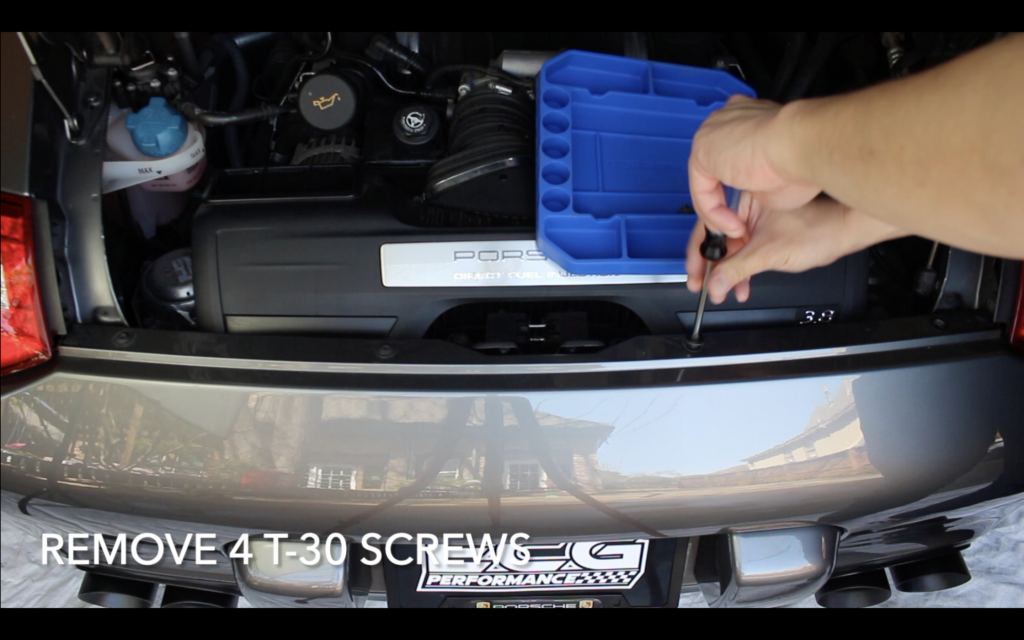
Step 26: Remove rear bumper (for exhaust valve controller installation)
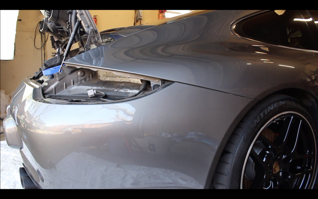
- Open engine deck lid.
- Remove 4 T-30 screws along top edge of bumper
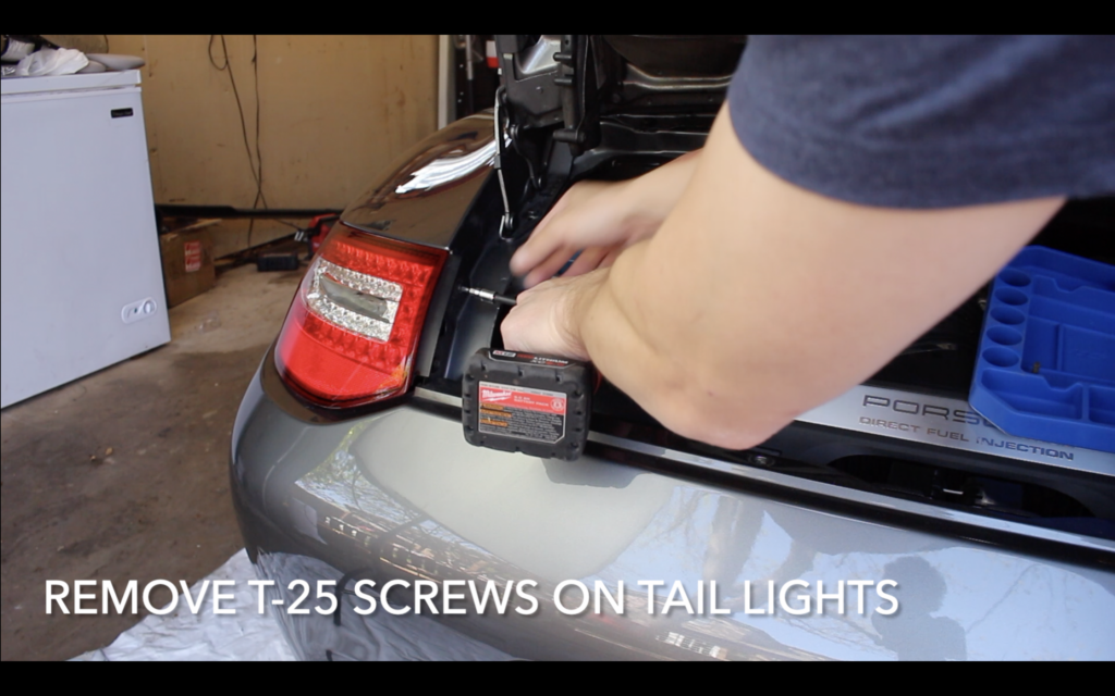
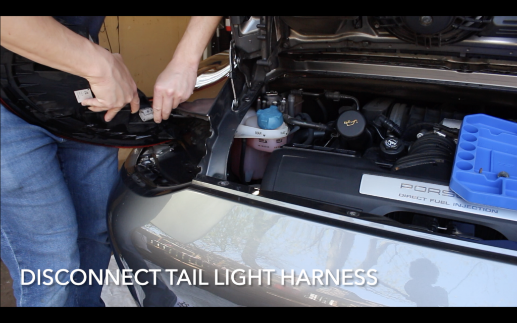
- Remove T-25 screws on each tail light, disconnect wiring harnesses, and then remove tail lights.
- With the tail lights removed, remote the T30 plastic screws that become revealed.
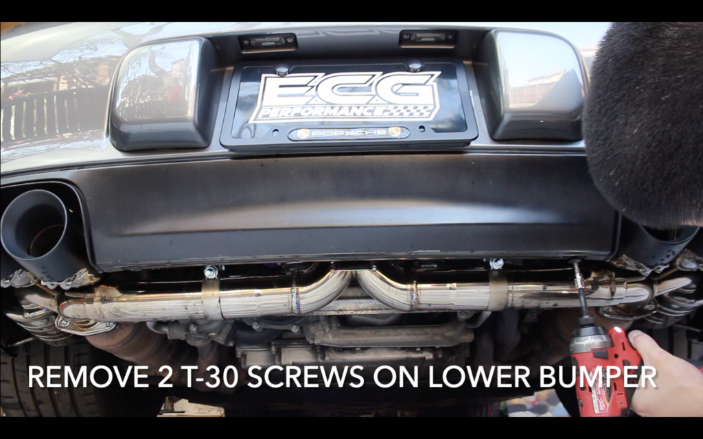
- Underneath the bumper, between the exhaust tips, remove the two T-30 screws.
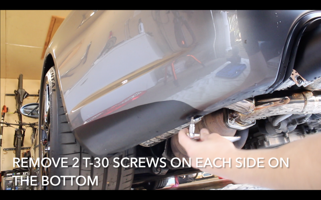
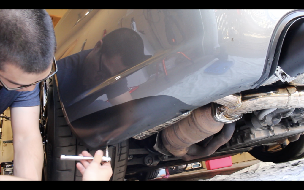
- Then on the lower edge of the bumper on each side, remove the two T-30 screws
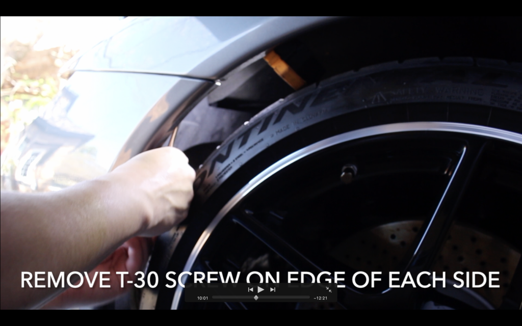
- Finally, where each side of the bumper meets the fender, remove the T30 screws on the inside of the bumper.
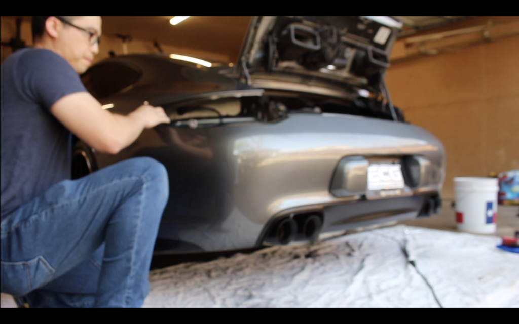
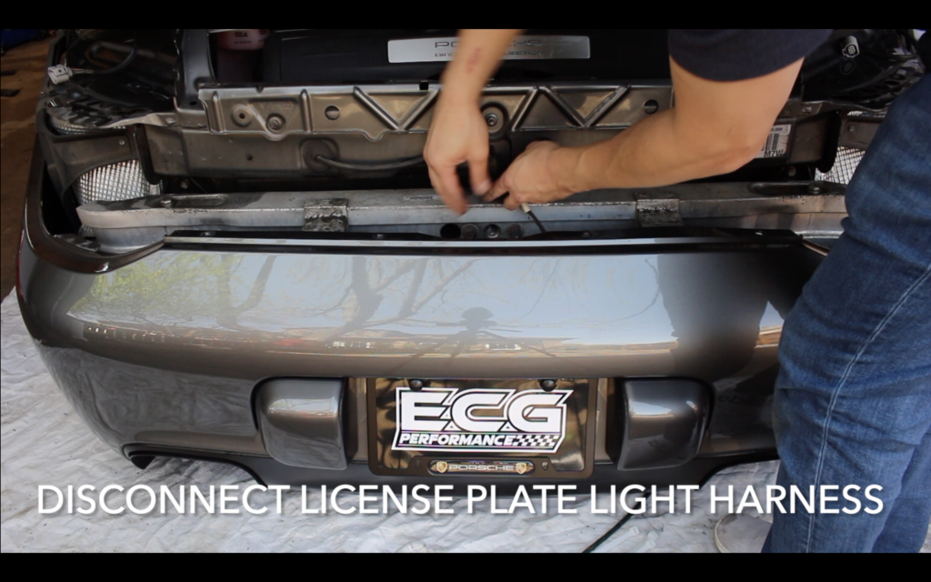
- Carefully pull each side of the bumper out to separate them from the wheel wells and then jiggle the bumper off; disconnect the wiring harness for the license plate light before fully removing the rear bumper.
Step 27: Connect hoses to exhaust valves
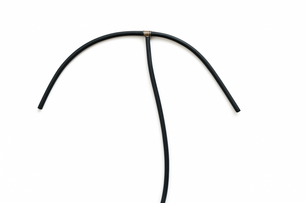
- Locate the hose that comes with the kit and cut two 15 inch sections.
- Connect the two 15 inch sections to the supplied brass t-fitting.
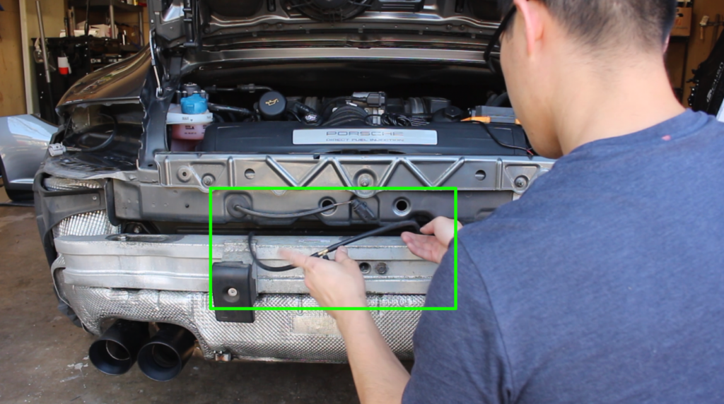
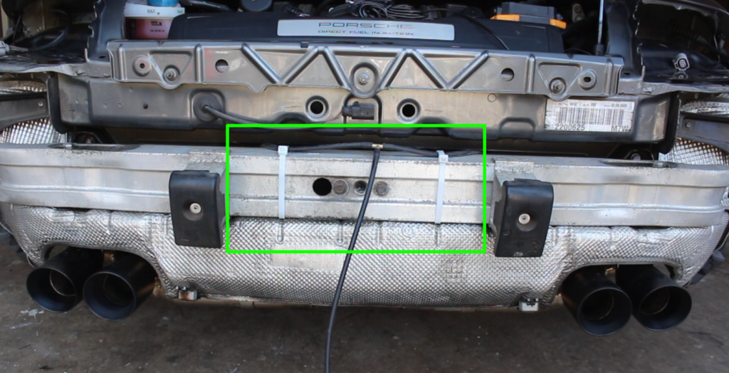
- Slip the two 15 inch hose sections into the space between the top of the bumper beam.
- Retrieve the two 15 inch hose sections underneath the car and connect them to the exhaust valves on the center muffler section.
- Secure the two hoses to the bumper beam using the supplied, white 24-inch zip ties; tighten the zip ties until the hoses are snug, but be sure not to pinch off the hoses.
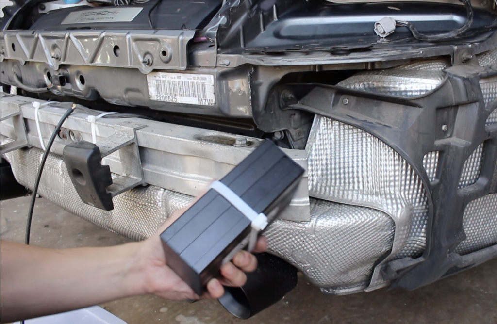
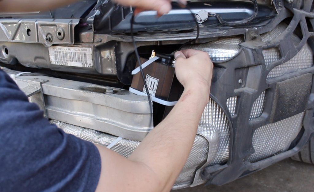
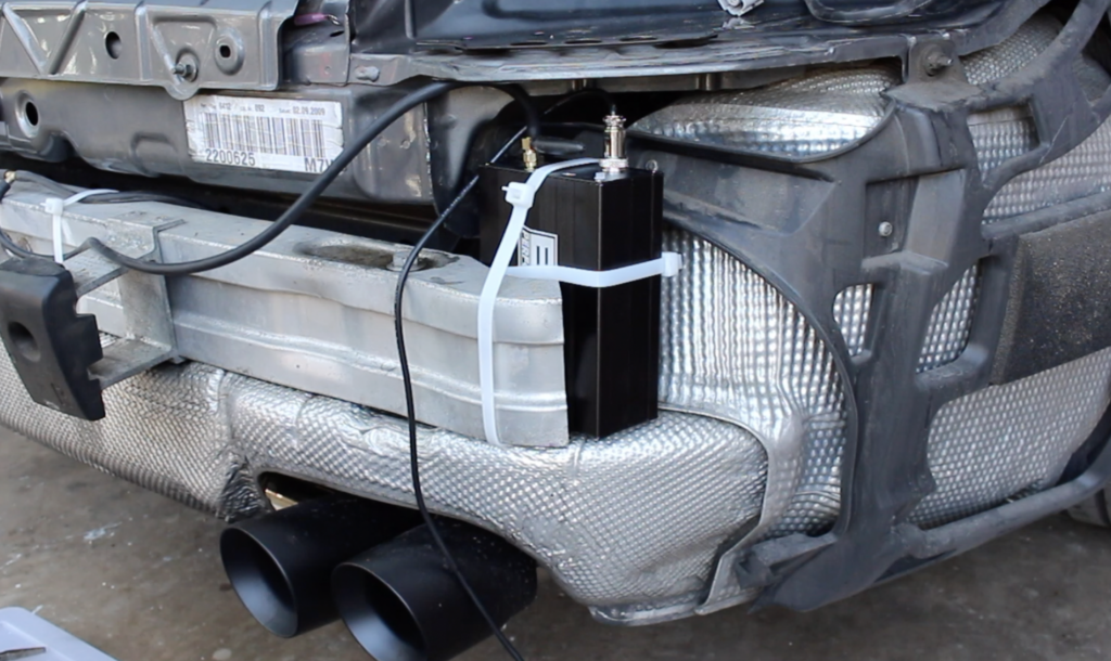
Step 28: Connect and mount the exhaust valve controller
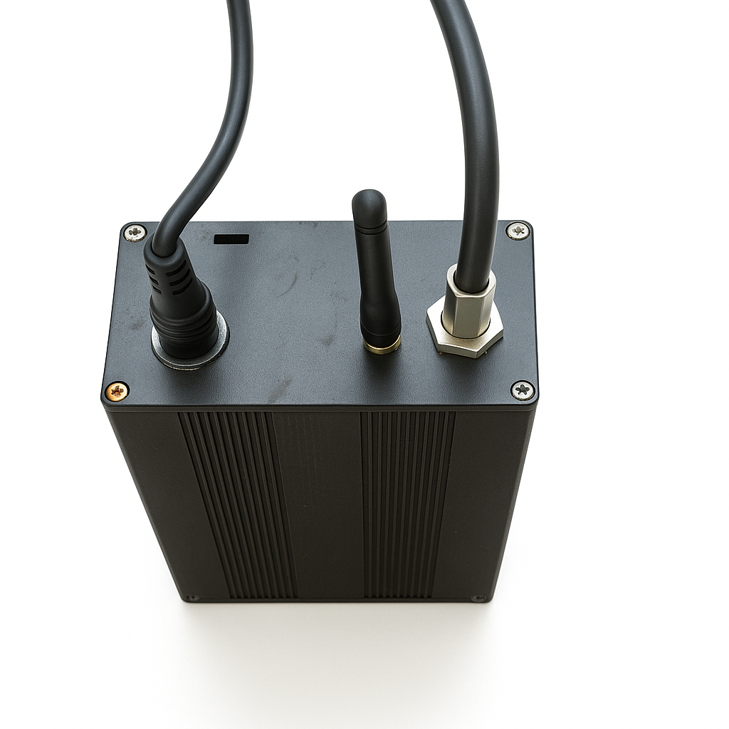
- Secure a 24-inch zip tie around the width of the exhaust valve controller; cut off the excess.
- Connect the vacuum line, small antenna, and power harness to the exhaust valve controller.
- Then loop a 24-inch zip tie underneath the right end of the bumper beam.
- Place the exhaust valve controller behind the right end of the bumper beam and loop the zip tie around the exhaust valve controller; be sure to loop the zip tie through the zip tie on the exhaust valve controller.
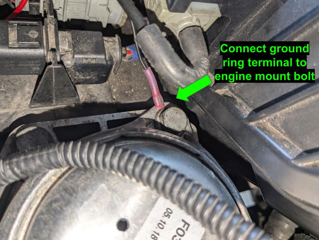
Step 29: Connect exhaust valve controller to 12V power
- For the ground wire, start by removing one of the 13mm bolts on the right-hand side engine mount.
- Loop the terminal ring on the ground wire through the 13mm engine mount bolt and reinstall the bolt; torque the engine mount bolt to 23 ft-lbs.
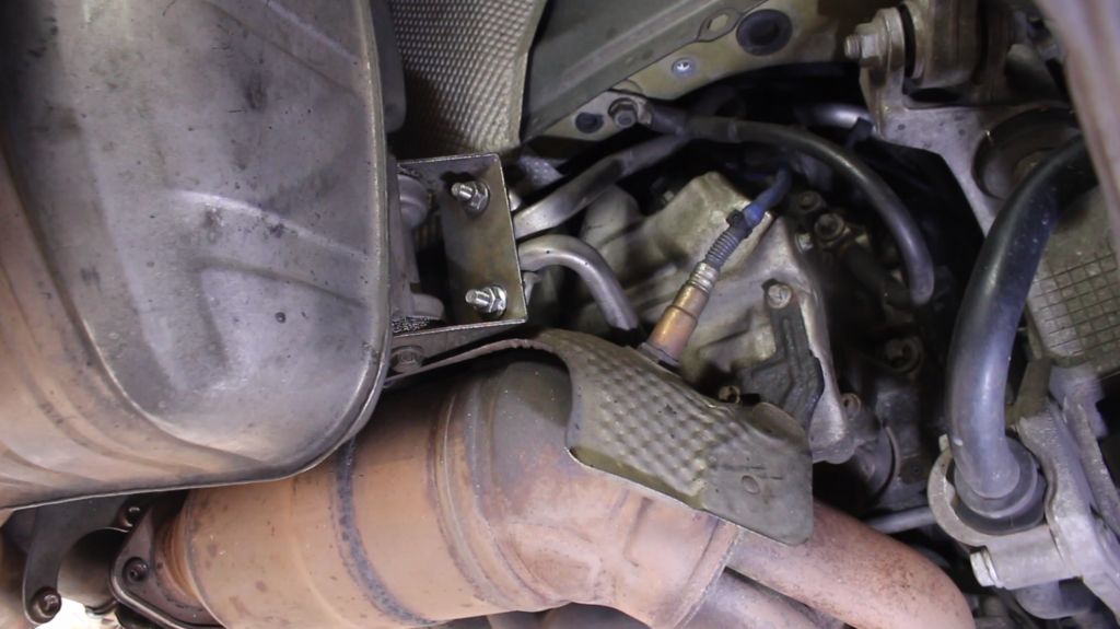
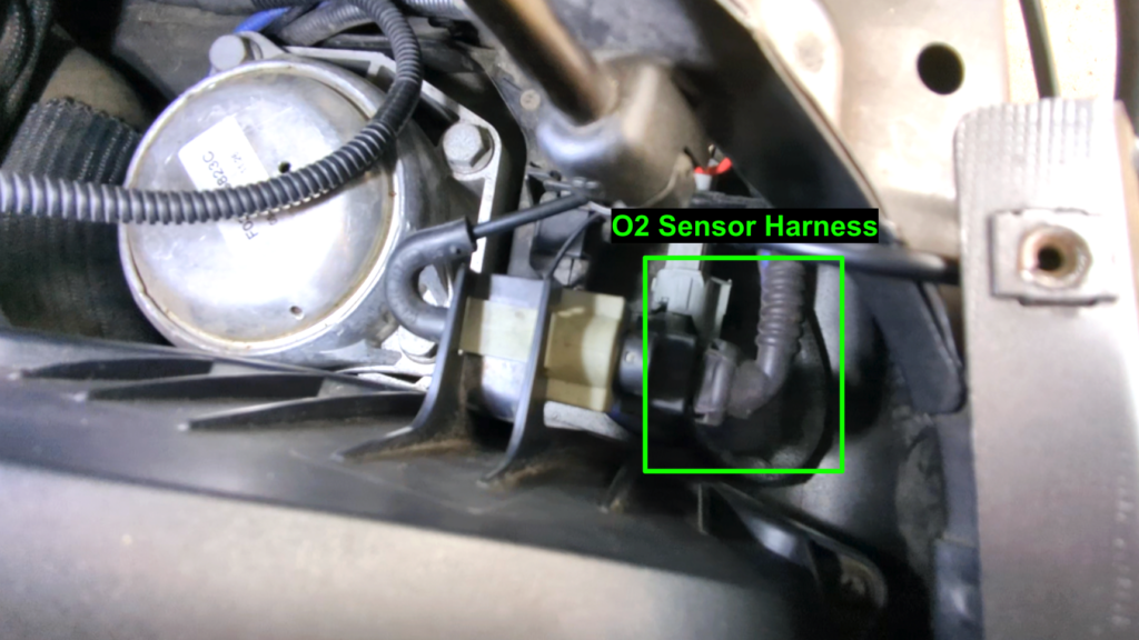
- For the power wire, first locate the O2 sensor, which is next to the engine mount; disconnect the wiring harness.
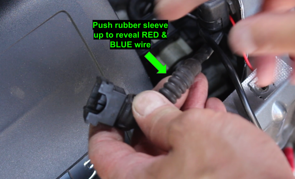
- On the O2 sensor wiring harness, push up the rubber sleeve and locate the RED AND BLUE wire.
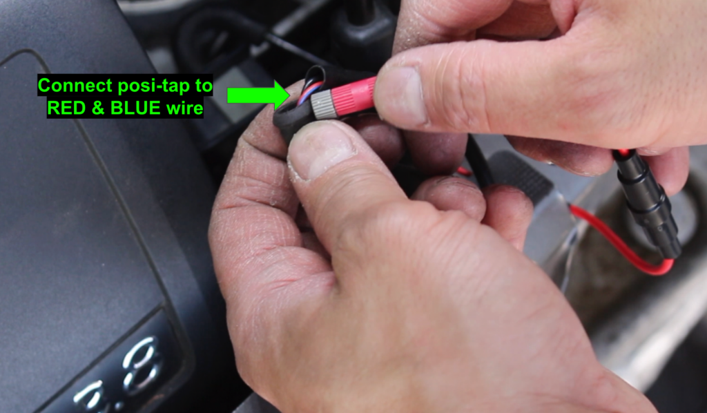
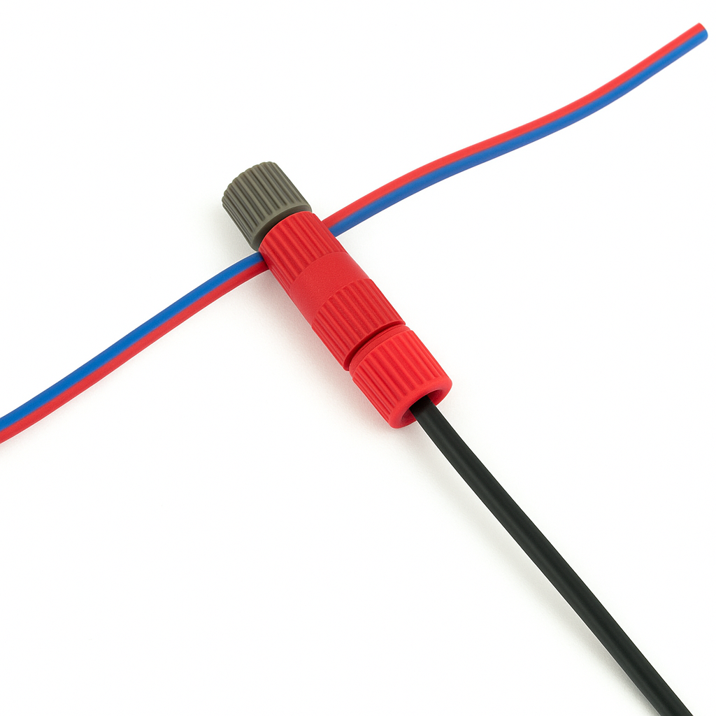
- Remove the gray end on the posi-tap connect, place it on the RED AND BLUE wire, then screw the posi-tap body onto the gray end; tighten the posi-tap until it is finger tight.
- Reconnect the O2 sensor wiring harness.
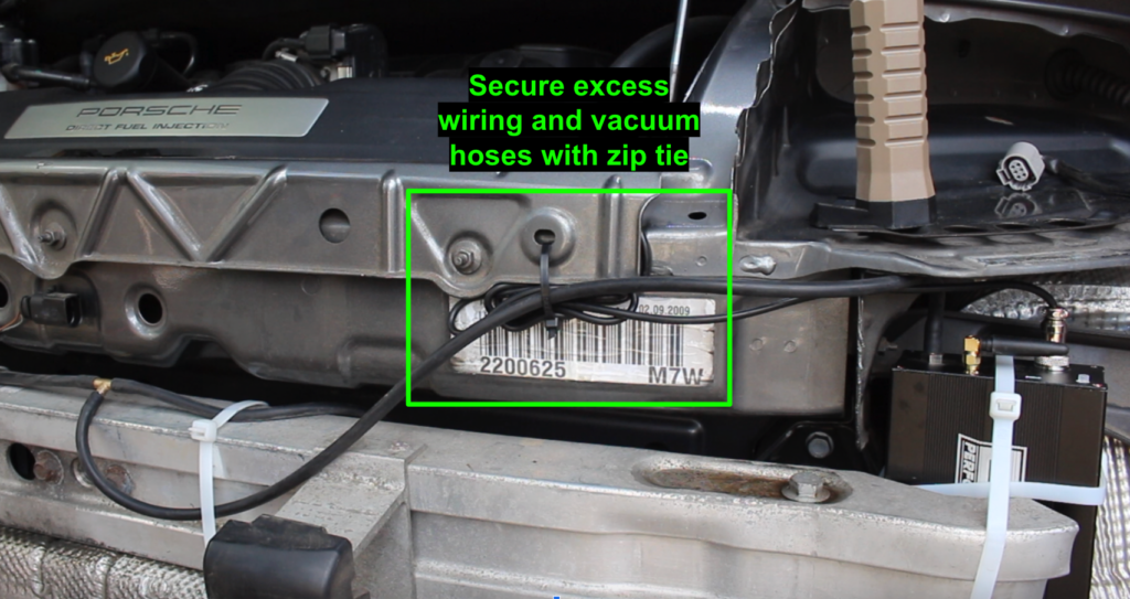
- Secure exhaust valve controller’s wiring harness and any excess vacuum hosing to the vehicle, as shown, using the supplied, 8 inch zip tie.
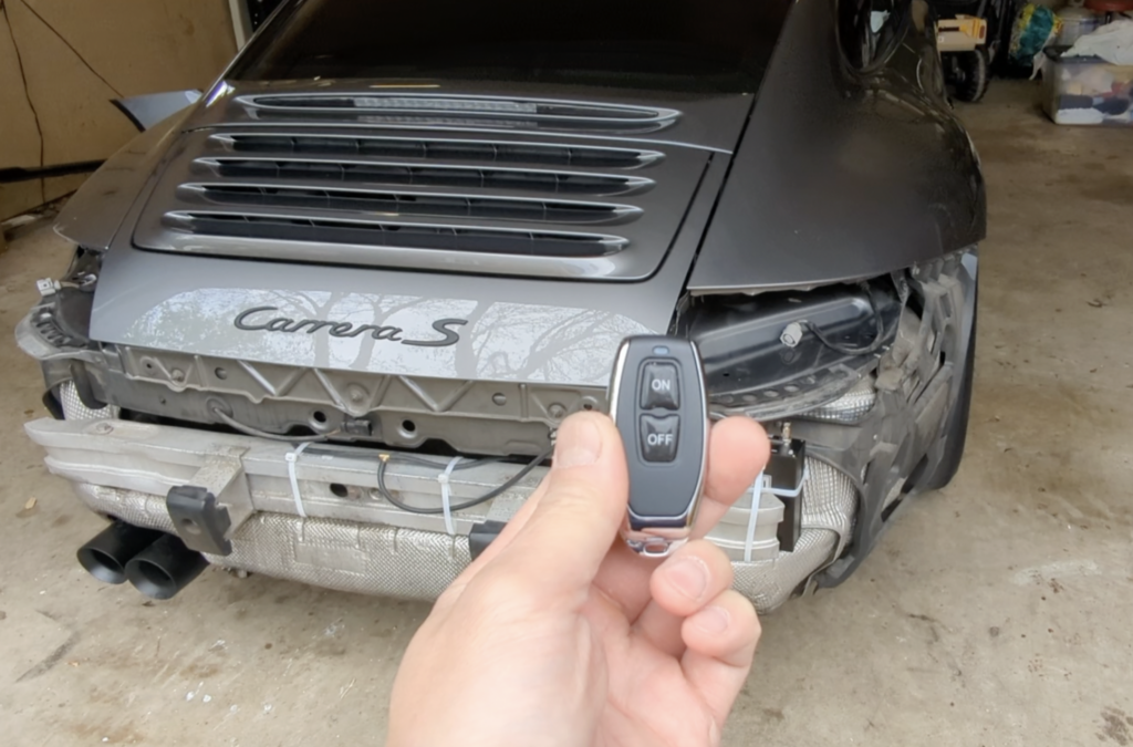
Step 30: Test exhaust valve functionality
- Turn vehicle ignition to “ON” position.
- Confirm exhaust valve controller lights up.
- Test exhaust valve functionality using the supplied remotes.
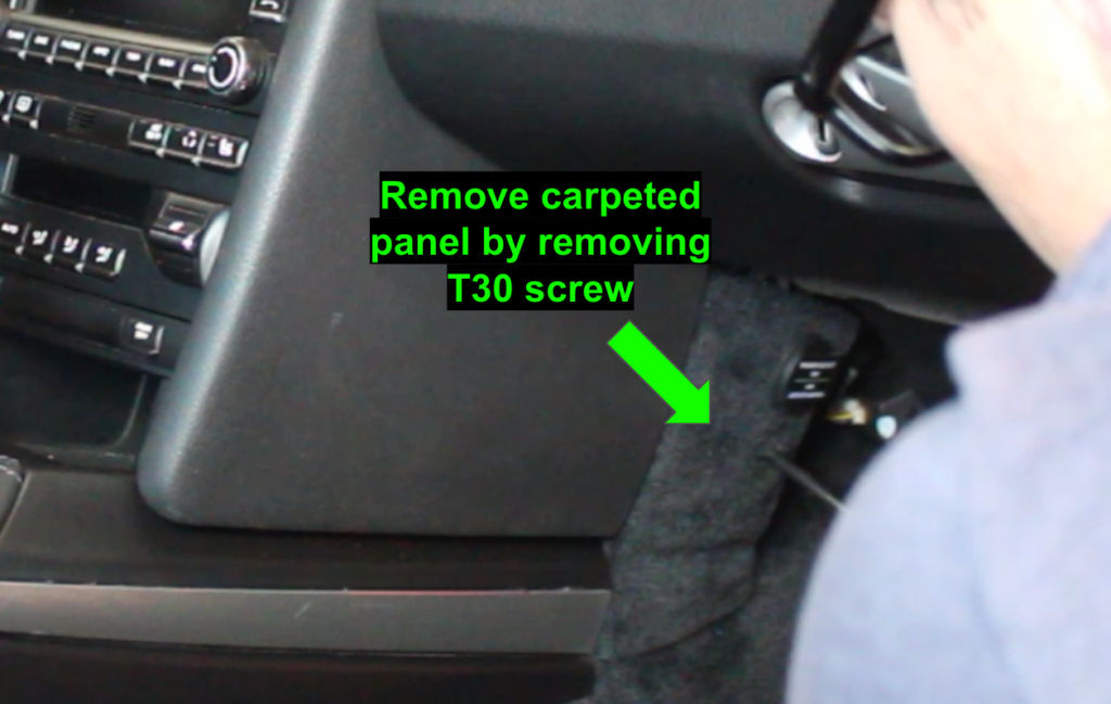
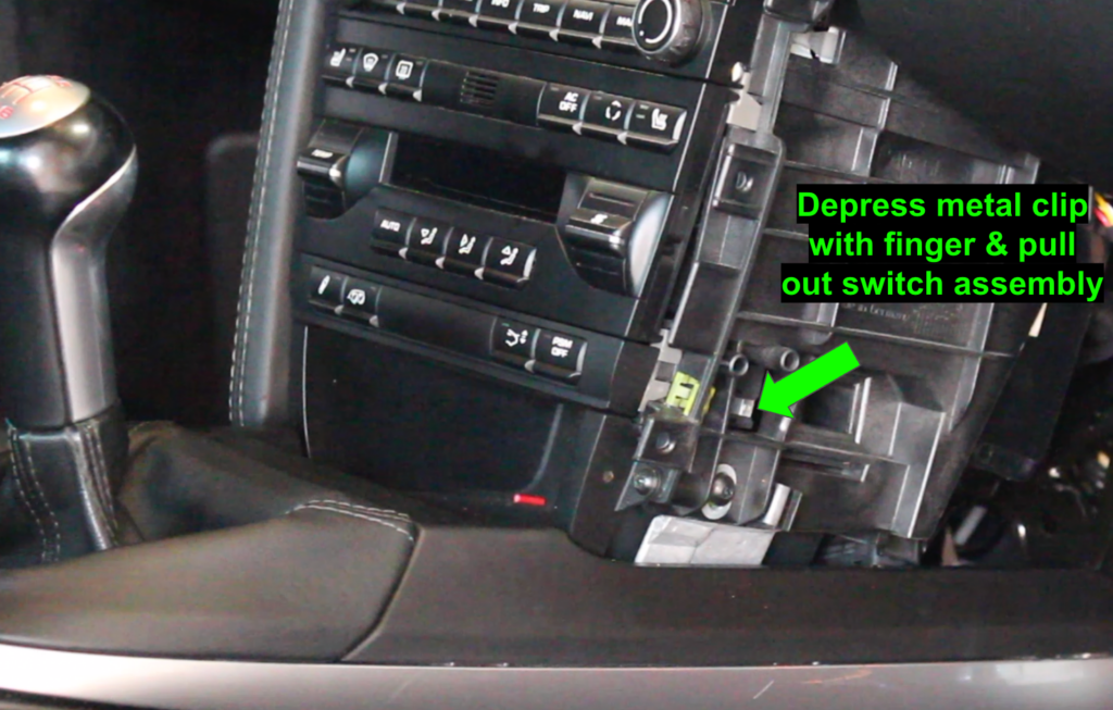
Step 31: ECG PSE Module - If optioned, begin by removing the center console switch assembly
- From the passenger seat, remove the carpeted panel containing the 12V outlet by removing a single T30 screw.
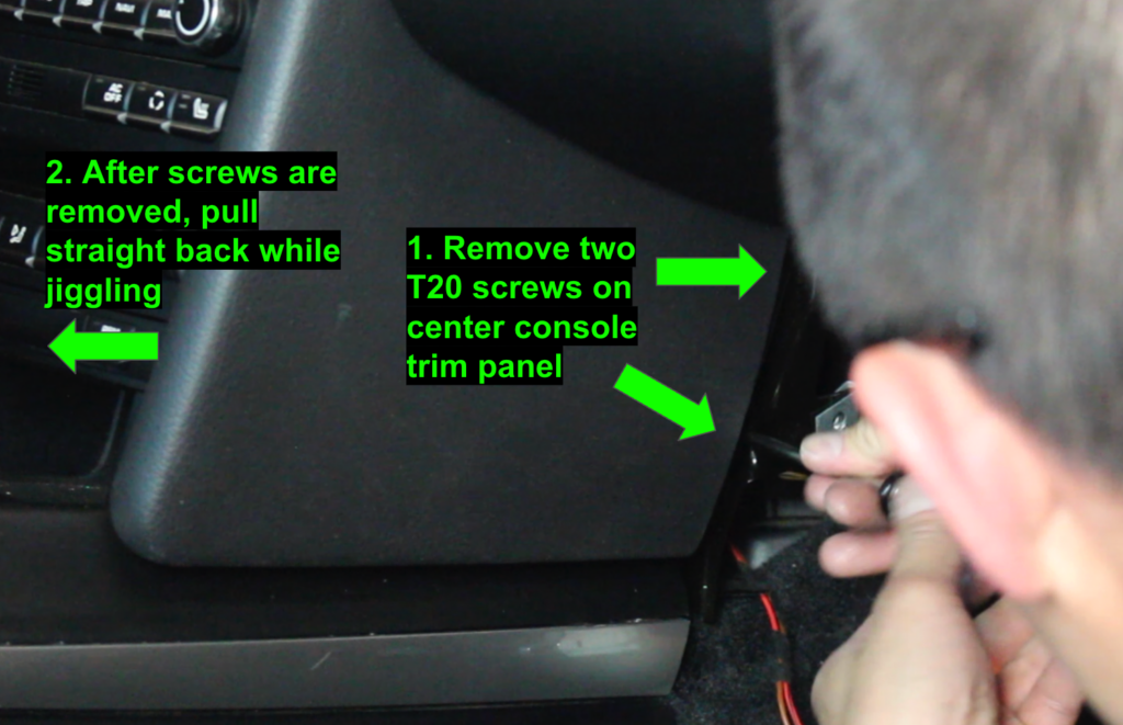
- Next, remove the two screws on the side of the center console trim panel.
- Then pull the center console trim panel straight back towards the rear of the car; carefully jiggle while pulling to avoid breaking any of the plastic tabs.
- Remove the center console switch assembly by depressing the metal tab on the side with your finger and carefully pulling; use a flat head screw driver to disconnect the red wiring harness from the switch assembly.
Step 32: Connect ECG PSE module to the switch assembly's wiring harness
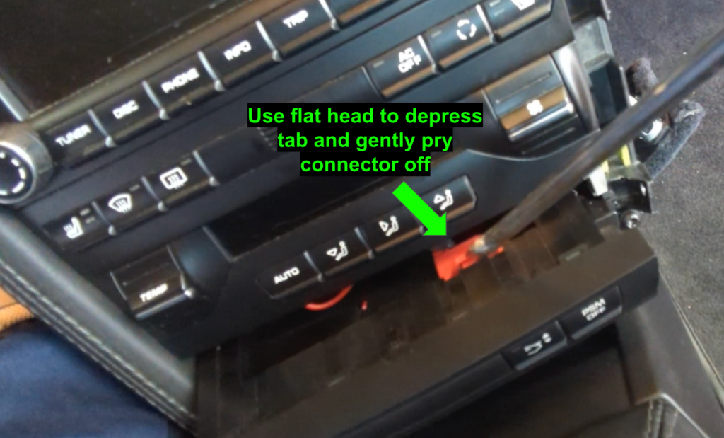
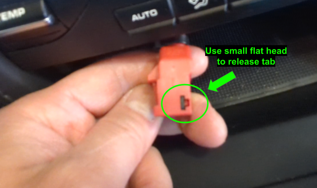
- Remove the red connector from the wiring harness by cutting the zip tie and, on the end (as shown), using a small flat head to release the tab; then you can slide the red connector off the wiring harness.
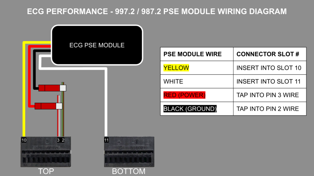
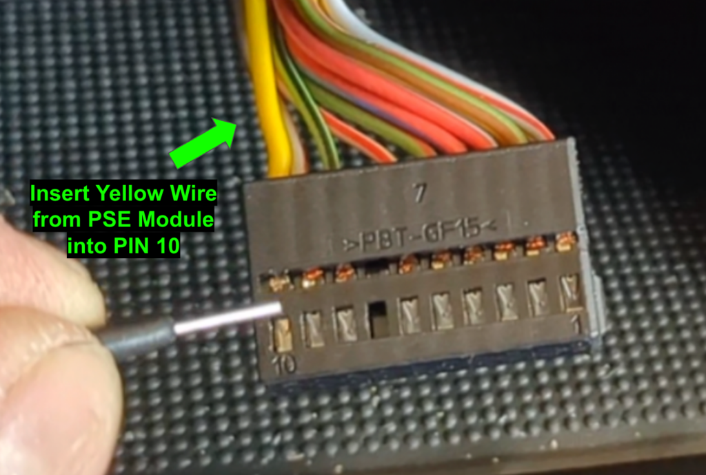
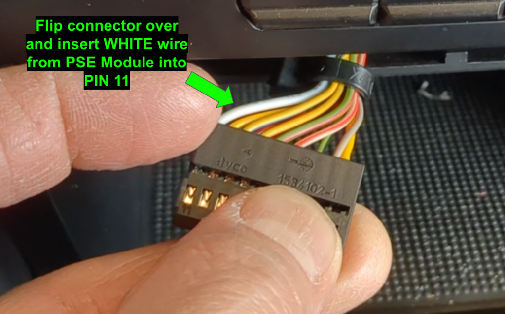
- As shown in the wiring diagram, on the black wiring harness connector, connect YELLOW wire to PIN 10 and WHITE wire to PIN 11.
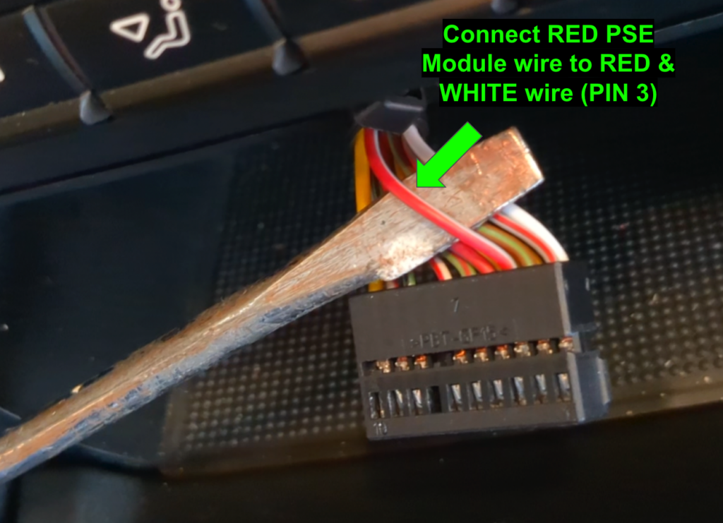
- Connect the RED power wire from the PSE module to the RED & WHITE wire going into PIN 3; be sure to place the posi-tap at least 2 inches away from the black connector.
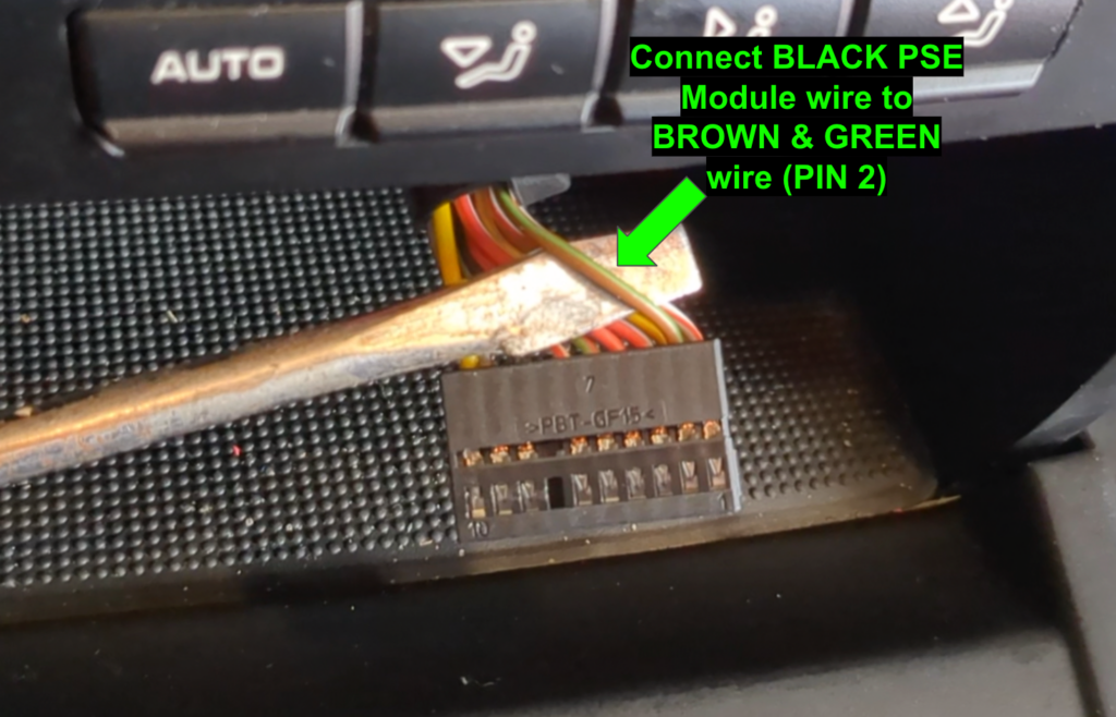
- Connect the BLACK ground wire from the PSE module to the BROWN & GREEN wire going into PIN 2; be sure to place the posi-tap at least 2 inches away from the black connector.
- Plug the black connector onto your new factory Porsche switch assembly (with PSE button), turn the ignition to the “ON” position, and test your new PSE button to make sure it works properly.
- Reinstall the red connector and use a new zip tie.
- Reinstall your new switch assembly, center console trim panel, and carpeted panel.
Step 33: Configure PSE module mode (if desired)
The ECG Performance PSE Module comes with two modes:
- Memory Mode (default) – Remembers your last valve setting when starting your vehicle
- Quiet Mode – Keeps exhaust valves closed upon startup.
By default, your ECG PSE Module ships with “Memory Mode.” To toggle between modes, hold the PSE button for 5 seconds until the LED flashes.
Step 34: Reinstall rear bumper, wheels, and return vehicle to the ground.
- Torque wheel bolts to 96 ft-lbs.